Driving home from work the other day, I saw this symbol light up on my dash for the first time:
Turns out modern cars have radio transmitters hidden inside their tires so they can tell you when they’re underinflated. Who knew?
My old bike pump used to have a pressure gauge built-in, but it sort of fell out, letting the air escape with it. I plugged the hole with a pen cap, so it could still pump, but it couldn’t tell me when to stop pumping anymore, so I picked up an AccuTire electronic pressure gauge with a Permanent Lifetime Lithium Battery.
That was years ago. I no longer own a bike. My previous car was a 1999 and thus unable to complain, so its tires had to wait until I went in for an oil change, which I did pretty regularly I guess.
So yesterday I break out the gauge, for maybe the 2nd time ever, and my left rear tire reads “L”. According to the fine print, that means I’m supposed to mail the gauge (not the tire) to New Jersey at my own expense so they can replace the battery free of charge.
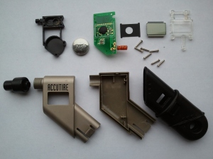
Instead, I take the gauge upstairs and try to open it. Turns out you can (a) unscrew the plastic nozzle and (b) peel back the rubber from the grip to reveal plastic tabs holding everything together. I eventually manage to push both tabs in at once and remove the handle. With nozzle and handle gone, the plastic casing falls into two halves and the innards pop right out.
There are 7 screws holding together a sandwich of plastic pieces on either side of the circuit board. Unfortunately, the battery is stuck in the middle.
With the screws off, one side of the sandwich slips right off. Not the side I want, of course. After a bit of prying, it emerges that the black piece that fits over the battery had been held in place by a bit of adhesive or sealant, right where the pressure sensor attaches. Whoops! I wonder if it’ll still be airtight when I put it back together.
Another surprise: the LCD isn’t attached to the circult board by anything more permanent than the pressure exerted by the plastic and the screws. I guess that helps explain why they went with gold plating for the PCB.
The battery itself is an ordinary-looking 3V lithium coin cell, CR-2032, the kind you find in everything. This one is firmly attached to one of the battery holder contacts by a little rectangle of black foam tape, which I scrape off with a small screwdriver. I dig through the battery drawer for a spare. No luck.
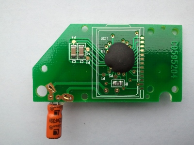
I’m distracted by this shiny printed circuit board. There is a tiny hole drilled through the PCB beneath the blue pressure sensor, presumably to prevent air from being trapped behind the sensor and giving a low reading.
And check this out: you actually see the bare die of the tiny chip labeled U2, through the soft transparent goop protecting it. Hair-thin bonding wires inside the goop connect it to the gold pads on the board. There’s a tiny black glob of goop under the chip, presumably just to stick it to the board. Usually these “glop top” chip coverings are black throughout, since semiconductors tend to respond to light as well as electricity. This one must be an exception, I suppose. Could be a signal amplifier for the pressure sensor.
The outer pads bracketing U2 are power and ground. You can see how they and the traces they connect to double as a shield to protect the analog signal on the inner traces from interference. Layout matters!
The main IC (U1) is entirely covered in the black stuff, as usual. Could be a general-purpose one-time-programmable microcontroller.
C3 is a thru-hole ceramic disc capacitor labeled 223, connected in parallel with the battery. 223 means 22 x 103 pF, or 0.022 uF. The giant orange cylinder sticking off the side a 22uF electrolytic capacitor, hooked up across the battery as well, with more of that clear glue to keep it from shorting. It’s called C4 on the PCB. Electrolytic capacitors used to be notorious for causing equipment failure when the electrolyte dried out after a few years, but the better ones are supposed to last longer nowadays.
C3, C4, and the battery (BAT-1) are each supplying power to the circuit, but on three different time scales. Cheap capacitors are often sufficient for this job. C3 takes care of high-frequency noise, C4 smooths out lower-frequency voltage fluctuations, and the battery keeps everything going for the long haul. Or not, as the case may be.
J1 and J2 are configuration jumpers. Each is a little glob of solder stuck to one of two pairs of pads on the PCB, like a switch that’s permanently set at the factory. Perhaps a different arrangement of solder would tell U1 to display a reading in kPa instead of PSI, for the non-US market.
The sensor side has gleaming gold test points TP1 through TP10. It’s a bit easier to do automated quality control if all of your test points are on the same side of the board. The MCU/LCD side has slightly smaller P1-5, perhaps used to program or calibrate U1 after the board is assembled.
R1 is a precision surface-mount resistor. I say “precision” because it has 4 digits printed on it, but I can’t quite read them, and my phone won’t focus that close. Should have done this in the workshop! C1 and C2 are unlabeled surface-mount ceramic capacitors, which are often of higher quality than the likes of C3 and C4. Their color indicates that they have relatively high capacitance for their size, perhaps as much as 0.1uF (as opposed to say 10pF, which would be light gray).
You can see a row of 13 gold contacts connecting the LCD (LCD-1) to U1. It looks like U1 drives the LCD directly, perhaps with a little help from R1, C1, and C2, but 13 isn’t enough to drive 24 or so segments independently (looks like 18.8.8 when it catches the light). It’s enough to drive one 8-segment digit at a time, though, including the decimal point or leading 1. Liquid crystals react slowly, so if the MCU switches quickly, the display won’t flicker.
It’s getting dark! I walk to the drugstore in the rain, buy a new battery, walk home, pop it in, and screw everything back together. The left rear tire now reads “01.0”. Huh! I don’t hear air escaping from that seal I broke, at least. The Internet’s suggested re-zeroing procedure has no obvious effect. Am I doing it wrong? I think I must have done it wrong. Hmm.
Jessica assures me that the gas station has a pressure gauge I can use, and even an air compressor. Sounds like a pretty sweet setup! Maybe I’ll swing by today and check it out….


2018-07-16 at 10:28
Did you ever get the Accutire pressure gauge working again?
2018-07-16 at 18:06
No, I did not.
2022-04-12 at 15:48
Lost calibration data from the factory by removing the old battery without keeping the circuit at 3V. I did the same to my Accutire and have the same result..