It’s been hot lately, so last weekend, on Blake’s advice, I stopped by the giant Longs and picked up a Lasko Cyclone Model 3540 20″ Power Air Circulator.
I’ve never owned a fan that came with its own remote control before. It has a built-in timer, too. It certainly seems to move a lot of air, even on the lowest setting.
It’s quite wide, which makes it a bit awkward to find room for it in cramped quarters. I was going to put it on top of a bookcase, but it turns out not to want to tilt down. I ended up stacking some books to make a little shelf for it in front of the window. It’s working well so far.
The most serious problem with this fan is the beeping noise it makes whenever you press any of the buttons, either on the fan itself or on the remote control. It even makes an extra-long beeping noise when the timer shuts the fan off after you’ve fallen asleep.
This is such a notable deficiency that Blake and I had actually discussed it at some length prior to my trip to Longs. I told him I thought it should be possible to correct the problem by cutting a trace on the circuit board, using a hobby knife or a razor blade.
In fact, it turns out to be easier than that. All you really need is a screwdriver.
Step 1: Unplug the fan.
Always a good starting point. Not that the plastic blades look all that dangerous to me, but there are some exposed high-voltage wires on the circuit board.
Step 2: Remove the front cover.
There are two long narrow Phillips-head screws on the back of the fan, a few inches above each hinge. Your screwdriver will need to be narrow enough to reach them. Mine wasn’t, but then I found another one that was.
Once the screws are off, the front cover comes out of its clips much more easily than before.
Step 3: Remove the circuit board cover.
If you look inside, underneath the pod with all the buttons and lights, you’ll see four screws. Remove the two larger screws, one from each side, and pull off the small plastic cover to reveal a mysterious green circuit board.
Step 4: Unscrew the circuit board.
There are four screws holding the circuit board in place, one near each corner. (The lower right screw is a bit farther away from the corner than the other three.) Unscrew those, and carefully remove the board from its housing, taking note of how the pieces fit together. You can also unclip the top plastic piece with the buttons at this stage, if you like. In fact, it might be necessary to do so. I can’t remember anymore.
Step 5: Disable the beeper.
The beeper is the round black thing with the little hole in the middle, over on the right side, labeled “BUZZER.” It looks like it would be a pain to remove it using average household tools. You could mute it somewhat by covering the hole with electrical tape, I imagine.
Chip U1, the small black rectangle just right of center, is an EM78P153S microcontroller. I had hoped it might be reprogrammable, but it isn’t.
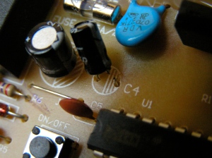
If you follow the traces on the green side of the board, you’ll soon discover that capacitor C4, the skinnier of two cylinders immediately above and to the left of the microcontroller, serves no purpose other than connecting the microcontroller to the beeper, through the magic of AC coupling.
I was able to cut one of capacitor C4’s little wire legs using a wire cutter.
A good pair of scissors might have worked almost as well. In fact, if you were to bend the capacitor back and forth a few times with your finger, the two legs would break right off with no need for any fancy “tools.”
Keep in mind that once you’ve disconnected this capacitor, it will be quite difficult to reconnect it properly, should you ever decide that you rather enjoyed having the beep after all.
Make sure that any remaining metal bits don’t touch each other. Otherwise you might sometimes get beeping and other times not. It is difficult to imagine anything worse!
Step 6: Put everything back together.
Reverse steps 4, 3, and 2 to reassemble the fan. The screws from each step are different, so this would be a good time to retroactively keep track of which is which. The two long narrow screws belong to step 2, the two wide screws are from step 3, and the four remaining medium screws came from step 4. Phew!
If all went well, you should now find yourself with a fully assembled fan that has working buttons, lights, and remote control, but absolutely no beeping!
Step 7: Blog about it.
This step is optional. In fact, I highly recommend skipping it.
Steps 1 through 6 took me 10 or 15 minutes at most. Discovering those first two screws, taking a few pictures, and looking up the data sheet for the microcontroller took another half-hour or so. Sitting down and writing about it has easily taken four hours. Crazy!
But, hey, I at least I have a blog now. In which I can, you know, blog about stuff. Bound to come in handy, right? Like when I someday decide to rejigger those hinges so the fan can point downwards. Won’t that be something?


